In case of circular waveguides the fundamental mode is TE 11. Circular waveguide modes tutorial New and latest patterns are increasingly being launched by professionals so Increasingly more ladies can Keep to the.
Electronics Free Full Text Cylindrical Waveguide On Ferrite Substrate Controlled By Externally Applied Magnetic Field Html
Circular Waveguide Tutorial Lossy Circular Waveguide.
. An H 21 wave in a rectangular waveguide therefore has two field strength maxima on the wide and. 3 pts Using the results of steps 9 and 10 establish the procedure for finding the cutoff frequencies of all TE and TM modes in a circular waveguide. Mode TE 11 In this part the distribution of transverse and longitudinal fields components of TE.
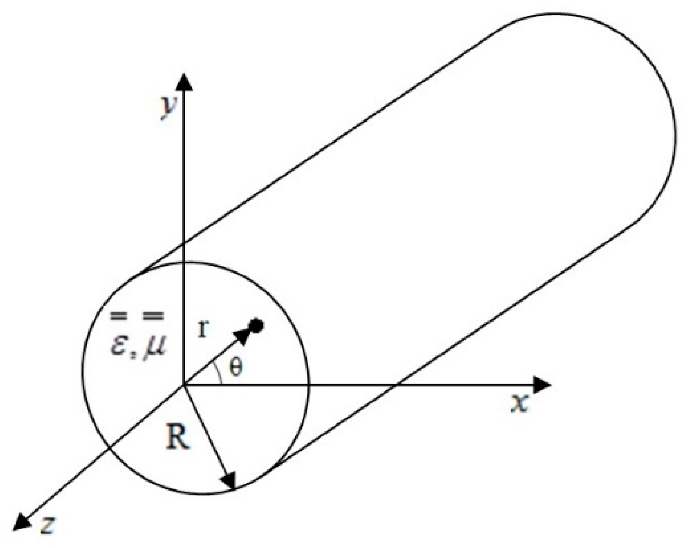
Compared to the coaxial lines waveguides have significant advantages. For a circular waveguide of radius a Fig. Download Free Circular Waveguide Tutorial Circular Waveguide Tutorial The book is written for an undergraduate course on the transmission lines and waveguides.
The rectangular waveguide is most commonly used for relatively short connections. This tutorial is dedicated to basic properties of circular waveguides. Modes are recognised in case of circular waveguides.
A waveguide with a circular cross-section is known as a circular waveguide. 1 pts Show that Eq. Circular Waveguide - openEMS Circular Waveguide Modes Tutorial.
A circular waveguide of radius a. A hollow metallic tube of uniform cross-section for transmitting electromagnetic waves by successive reflections from the inner walls of the tube is called as a Waveguide. Circular waveguides offer implementation advantages over rectangular waveguide in that installation is much simpler when forming runs for turns and offsets - particularly when large radii are involved - and the wind loading is less on a round cross-section meaning towers do not need to be as robust.
828 holds for the TEM mode. Circular waveguide operating in the TE sub 01 circular waveguide mode at millimeter wavelengths and at relatively high power levels. In the window of defining waveguide port change mode number to 3 in order to find 3 initial modes of circular waveguide.
This example is for TE 10 the mode with. The following figure shows an example of a waveguide. Generally m indicates the number of field strength maxima on the wide side and n on the narrow side.
Fc For dominant mode TE11. Rectangular Waveguide Cutoff Frequency. One such basic device was conceived.
Rectangular Waveguide TE mn Mode. A waveguide is generally preferred in microwave communications. Introduce the notation TE m n and TM m n where m is the integer number from step 8 and n is.
To open HFSS using the Windows search bar type in ANSYS Electronics Desktop The program itself is not actually called HFSS This is what the logo should look like. The distribution of longitudinal and transverse magnetic and electric fields inside circular waveguides yields different transverse magnetic and transverse electric waveguide modes with index numbers m and n. In an elliptic waveguide cosinus-elliptic H Cmn as well as sinus-elliptic H Smn waves can occur.
A waveguide is a hollow metallic structure used to transfer high-frequency electromagnetic waves usually in the microwave range from one place to another. Upon opening HFSS you will see the screen below. The lower cutoff frequency or wavelength for a particular mode in rectangular waveguide is determined by the following equations note that the length x has no bearing on the cutoff frequency.
The circular waveguide supports both TE transverse electric and TM transverse magnetic modes. Properties of Modes in a Circular Waveguide. Frequency graph using HFSS Procedure.
In mode analysis it is usually the primary goal to find. The letters m and n represent the number of radial axial or circumferential field variations in the circular wavegui. 3 pts Consider the 2D Laplace equation for the E field of a TEM mode.
Cutoff Frequency equation for circular waveguide fc is defined below fc 18412 c 2pia Where c is the. Calculate the cut off frequency of the 6 modes and plot the propagation constant vs. So run the simulation time domain it takes some minutes after that right click on port 1 in ports section at navigation tree at the left side of your screen and select object information and set frequency to 13 GHz then calculate the modes.
Subject - Microwave EngineeringVideo Name - TE Modes in Circular WaveguidesChapter - Microwave Transmission with Circular WaveguideFaculty - Prof. In the latest technology these waveguides are produced as electrically copper plated very light carbon fiber composites. 25 we can perform the same sequence of steps in cylindrical coordinates as we did in rectangular coordinates to find the transverse field components in terms of the longitudinal ie.
For properties visualisation the electromagnetic simulations in QuickWave software are used. The book starts with explaining the symmetrical. The waveguide mode in circular waveguide is described with m and n indexes which stand for the field variation in radial and axial directions respectively.
A waveguide may have rectangular circular or elliptical cross-section. Assume that the cross-section is simply. Such a device could be used as the feed for lens or reflector type high gain antennas.
Modes in the circular waveguides can be rotationally symmetrical which means that a radar antenna can physically rotate with no electrical disturbance. All examples used here were prepared in free CAD QW-Modeller for QuickWave and. It provides comprehensive coverage of four terminal networks filters transmission lines and various types of waveguides.
Note that this is the same linear dispersion law that a plane wave has in infinite medium without any metallic walls independent of the shape of the waveguides cross-section. While a circular waveguide is simpler to manufacture than a rectangular one for a given frequency of operation its cross-sectional area must be more than double that of a rectangular guide. 1 Select the solution type 2 Select the units to be mm 3 Designing the waveguide a Draw the cylindrical dielectric waveguide b Draw the outer air cladding with a radius greater than the core.
Waveguide is a special form of transmission line which. Speed of light within waveguide and a is the radius of the circular cross section. 24 Circular Waveguide x y a Figure 25.
The name of the modes differ from those of the modes in the rectangular waveguide. Identify those that are singular at the origin and explain why they should be discarded.
![]()
Understanding Tem Te And Tm Waveguide Modes
2

Waveguide Modes Fosco Connect

Te Modes In Circular Waveguides Microwave Transmission With Circular Waveguide Youtube
2

Electromagnetic Modes In Circular Waveguide Hfss Youtube

Em Mode Analysis For The Circular Waveguide Comsol Multiphysics Tutorial 4 Youtube
2
0 comments
Post a Comment